Tandem Mounting
The ability to tandem mount units can often overcome issues related to space, speed of prime mover vs. rated hydraulic pump speed, and displacement of pump.
Space
The space issue may be because of:
- The total area available to fit the power unit into.
- The area available to fit certain components into.
Reducing the number of electric motors and starters can significantly reduce the space required and will also reduce the cost in many instances. Also the size of the hydraulic tank makes closed circuit more compact than open circuit.
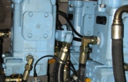
Tandem mounting two smaller units rather than one large unit can help if a splitter gear box is used or the area is confined. A good example of this is on a deck crane. Due to the small diameter of the pedestal there is not enough room to mount a standard P14 (229 cc/rev) pump but by tandem mounting two P7 (119 cc/rev) units together the same result can be achieved.
Speed of the prime mover
As pumps and motors get bigger in displacement the maximum RPM they can operate is typically reduced.
If a standard electric motor or diesel engine is required as the prime mover and the operating speed is too high for the pumps to run at then tandem mounting two smaller units may overcome this problem. A good example is of a 60 Hz (1800 PRM) system requiring a 1000 cc/rev displacement. If we consider a 1000 cc/rev pump which has a maximum speed of 1600 RPM (non standard electric motor) then this will not work. However we can use a tandem 500 cc/rev unit and meet the requirements.
Displacement of pump or motor
As units have a maximum operating speed, using two smaller units to meet the requirements may be a better option. This can also be beneficial when the flow requirement of the system falls in between the sizes of pumps or motors available. Using a 750 cc/rev unit to meet the requirements of a system requiring 620 cc/rev is very inefficient, where using two units running at full displacement would be a better option. This is certainly the case when the speed has to be variable up to the maximum flow requirement.
Operating in neutral for extended periods
Most systems are meant to be working all the time when the electric motor/diesel is running. However in the real world many applications leave the electric motor/diesel running while waiting for some activity to restore the machine to a working mode.
Some examples: Cranes, Conveyors, Winches, and Process machinery.
Although the waiting times are supposed to be minimal in reality they can stretch into hours and sometimes days and regardless of the consumed power the electric motor can be left running which can create a lot of system heat and is very inefficient.
Operation in neutral diagrams
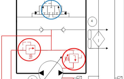
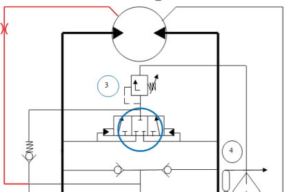
In neutral the hot oil shuttle is blocked (Item 3) and there is no oil going from the circuit back through the cooler and filter to tank. In fact all the oil from the servo and boost pump (Item 6&7) is going across the servo and boost relief valves and into the case which will cause the oil to heat up. At the same time there is no oil at all going through the cooler!
- Main pump P24P
- Motor
- Shuttle valve
- Cooler
- Return filters
- Servo Pump
- Boost Pump
The only advantage to this is that the pump case is getting flushed to help keep the case temperature down but eventually the tank temperature will keep rising and the system will overheat.
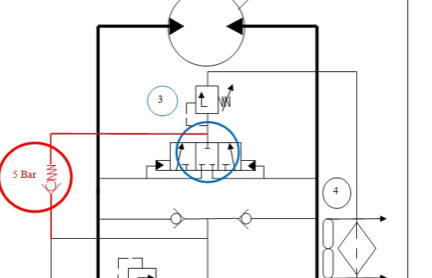
To resolve this heating issue, a 5 Bar (65 psi) check valve and a few hoses can be installed as shown. This will provide continuous flow through the cooler in the neutral position.
However now that the flow is going across the 5 Bar Check valve through the cooler, filter and back to tank there is little oil flowing through the case of the pump. This will make the pump case run hot and will reduce the life of the unit.
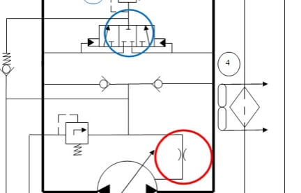
To rectify this we remove the internal pilot valve and filter from the valve block and introduce an orifice.
The orifice can be sized to suit the application but a standard 2 mm (0.080”) with a 15 Bar (220 psi) charge pressure is sufficient to flush the case with approximately 7 l/min (2 gpm).
This also means that the boost pressure is set on the shuttle valve at say 15 Bar (220 psi) and when the pump is in neutral this rises to 15 + 5 = 20 Bar (291 psi) and will drop again to 15 Bar when the pump is stroked.
If cooling for the motor is also required then adding another line with an orifice will also ensure the motor is flushed with cool oil.
It is also recommended that the case drain filters for the pump and motor cases do not have by-pass check valves but are fitted with a pressure switch for warning and shut down.
Understanding Pump Case Pressure (Open Vs. Closed Circuit Systems)
Case pressure may cause more pump failures than any other in Open circuit pump systems and is usually not even recognized as the cause of the problem. Designing a closed circuit system with Gold Cup can provide a real advantage over open circuit designs. Unless there is a requirement for case pressure all case drain fittings and hoses should be low pressure. We are trying to keep case pressure to an absolute minimum so we do not need high pressure hoses and fittings in the case drain. You should be able to squeeze the hose with your fingers!
Case pressure should be considered different when designing for open verses closed circuit systems.
Detecting case pressure spikes: Pressure transducers are the only good method of measuring case pressure. Even low pressure gages are not suitable, as they are not able to catch transient spikes.
Case Pressure – Open Circuit
There are two different case pressures to consider:
- Maximum case pressure allowed (Peak): Pumps usually have a maximum case pressure given which is normally the maximum case pressure allowed before shaft seal failure and leakage occurs.
- Maximum operating case pressure: Maximum operating case pressure is usually lower than peak pressure and is directly proportional to the inlet pressure of the pump. If we consider a typical open circuit piston pump, you may see that the Maximum Peak Case Pressure is 3 Bar (13.5 psi). However the Maximum Operational Case Pressure is only 0.5 Bar above the inlet pressure. Usually the inlet pressure is at atmosphere which is zero gauge pressure, therefore the max pressure we can have in the pump case in this condition is 0.5 Bar (7 psi).
Case vs. Inlet
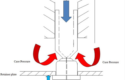
If the case pressure exceeds 0.5 Bar above the inlet pressure then as the piston is drawing oil from the inlet, case pressure will push against the piston which pulls the shoe against the retainer. The piston is then pushed with the pressure against the creep plate and this is a continuous cycle up to the maximum pump driven speed depending on the prime mover. This repeated motion will eventually loosen the shoe on the piston and cause catastrophic failure.
Case Pressure – Closed Circuit
We do not have the same restrictions with a closed circuit pump!
Due to the fact that we have a boosted inlet on a closed circuit pump and the boost pressure is always a positive pressure on the inlet to the pistons in the barrel. If we consider the Gold Cup pumps this should be a minimum of 10-12 Bar (145-175 psi). This means that we now have the opportunity to have a case pressure up to the maximum permitted which for continuous use is 5 Bar (75 psi).
This means we can now have case drain filtration (Highly Recommended) to protect the circuit from contamination wear or premature failure.
Causes for Increased Case Pressure
Restricting the case drain back to tank by:
- Reducing the size of the pump case drain port
- Using high pressure hose and fittings (reduced internal diameter) A low pressure hose also has the ability to act as an accumulator to take care of any pressure spikes.
High flow through the case (Frequent use of the compensator or servo control)
Also any restriction of the inlet to the pump will also cause problems because the inlet then becomes a negative pressure (vacuum). This is more of a concern for open circuit pumps and can be due to:
- A hose or fittings which are too small
- The use of a suction strainer
- Restriction of oil back to the tank
What can cause increased case pressure?
Restricting the case drain back to tank by:
- Reducing the size of the pump case drain port
- Using high pressure hose and fittings (reduced internal diameter) A low pressure hose also has the ability to act as an accumulator to take care of any pressure spikes.
- Frequent use of the compensator or servo control
Also any restriction of the inlet to the pump will also cause problems because the inlet then becomes a negative pressure (vacuum). This can be due to:
- A hose or fittings which are too small
- The use of a suction strainer
- Restriction of oil back to the tank
Soft Start
Soft Start
The Gold cup pump is unique and has some features which need to be understood where unusual requirements or circumstances may occur such as:
- Due to a power failure the system is shut down with the pump still on stroke.
- The system must not under any circumstances be capable of supplying pressure or flow until a specific condition is reached.
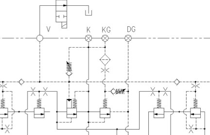
Both of these circumstances can be controlled by the use of a vent valve connected to the pump “V” port with a solenoid or manual on/off command.
One of the unique features is that the stroking mechanism does not have any centering springs and can only be controlled when servo pressure is available.
When the system stops due to a power failure then the pump can be left in an on stroke position. With a soft start (star delta) starter it is not possible to re start the pump due to the power requirements to overcome the flow and pressure capability of the system. Re starting the system with a zero flow command, and the “V” port vented, the servo will bring the pump back to a zero position. Depending on the stopping position this may take several starts to achieve this.
Under start up conditions the valve is deactivated and connects the pressure control of the pump to tank i.e close to zero pressure. When the required condition is reached then the valve can be activated which will allow the pump to function as normal.
NOTE: This should not be used as an emergency stop unless an orifice is installed between the V port and the directional valve. This reduces rapid stroking and component fatigue.
Remote Servo/Boost Supply
Remote Servo/Boost Supply
The Gold Cup pumps can be configured with or without the servo/boost pumps integrated. As these are critical requirements for the pump and the system, having them as part of the pump is the normal configuration. However there are applications and circumstances where an external supply of these requirements is advantageous:
- Critical start up conditions
- Off line cooling/heating and filtration
Critical Start-up Conditions
Some systems require that all the pipe work is full of oil and at boost pressure before the main pump is started. This can also apply to servo pressure where the system relies on the servo pressure to activate a critical component or safety valve. We can also use this pressure to ensure that the main pump is in a neutral condition for start up. Although using an off line supply for these functions requires additional pumps, starters etc it achieves the requirements with a vastly reduced power consumption and can run in this condition for extended periods at reduced cost to the end user.
This method is also advantageous for some hydraulic components which due to their design will drain the oil from their cylinders/pistons and need to be pre filled before start up. Radial Piston motors are one example.
Off-line Cooling, Heating & Filtration
Many times the requirement for off line cooling/heating or filtration dictates that external pumps to the main system pumps are required. Again these can run for extended periods of time with a low power requirement and can be combined with the requirements above in many cases.
Heating the system up in cold climates or conditions is very common in remote, offshore or artic type conditions. The oil is brought up to operating temperature and then the system is flushed with this oil before starting the system.
The off line filtration/cooling is usually combined to ensure that the oil in the tank is kept at an optimum temperature and the cleanliness of the oil is maintained at a level which prolongs the life of the oil and system components.
Servo Flow
What is servo flow?
Servo flow is the fluid used by the control to move the cam (+/- 100% or +/-19 degrees) to achieve full output flow from the pump in system ports A or B. Servo flow can also control the motor cam between zero and full displacement, to obtain the desired speed or output torque.
Where does servo flow come from?
Servo flow typically comes from an internal charge pump but can also be plumbed to the Gold Cup from a rear mounted auxiliary pump or an external source.
How much servo flow is required to obtain published catalog response times (as shown below)?
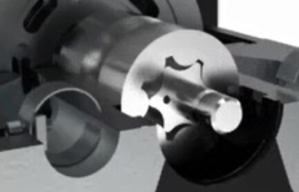
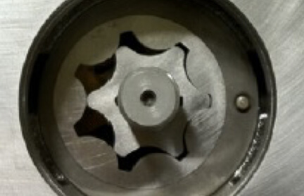
Approximately 2 gpm ( 7.6 lpm) is sufficient. Note: The standard gerotor (see below photo) used in the small and mid-frame size Gold Cup pumps is 1.07 in3/rev (17.5 cc/rev) and provides 5.5 gpm (21 lpm) at 1200 rpm. Any remaining flow not used to stroke the pump will spill to the replenish gallery.
From zero to full stroke or back:
- P6 / P7 / P8 = .9 seconds
- P11 / P14 = 1.5 seconds
- P24 / P30 = 1.8 seconds
Can and should servo flow be filtered?
Yes, servo flow can be externally filtered and it’s never a bad idea to ensure clean fluid is sent to your pump control. In some cases, a modified control or port block is required to filter the flow, depending on pump frame size and control location (please contact hps.technical@support.parker.com if modified components are required for your application). Reference Pump BRIEF AS-0018 for hydraulic schematics and filtering solutions.
Servo Pressure
What is servo pressure?
Servo pressure is typically regulated internally by the Gold Cup to a level that enables the pump or motor to be controlled and positioned to full displacement under maximum operating conditions.
Can I set the servo pressure?
For standard Gold Cups, the servo pressure is automatically set based on the factory replenish pressure set point, and then increases proportionally with a rise in system pressure.
Modulating pin feature within the valve block automatically increases servo as below:
- P6, P7, P8, P11, P14 Units: 40 psi increase for every 1000 psi increase in system pressure
- P30 Units: 60 psi increase for every 1000 psi increase in system pressure.
What if I want fixed servo pressure?
Fixed servo pressure can be obtained two different ways using special valve blocks. The first way uses a valve block with blocked servo poppet and servo would be fed and regulated from an external source. The second method would use a valve block with special servo poppet components (typically including a heavier servo poppet spring) and no modulating pin. This will elevate servo pressure in relation to replenish pressure and will not change as system pressure increases. See more information about this topic in our Valve Block section.
What is the minimum servo pressure and what happens if I go lower?
Minimum servo pressure is dependent on system pressure and how far you wish to stroke the pump. The lower system pressure and stroke angle, the lower servo pressure is required. The modulating pin feature in the valve block automatically increases servo pressure as system pressure increases to ensure servo pressure can overcome the internal forces required to hold the pump at full displacement at maximum rated pressure. If you operate with an external servo supply that is too low, then the pump will not be able to stroke to full displacement over the entire operating pressure range.
What is the maximum servo pressure and what happens if I go higher?
Maximum servo pressure is 1000 psi, however, we recommend servo pressure be limited to around 750-800 psi. The benefits gained in response time are minimal once you go beyond 750 psi. Operating at elevated servo pressure can lead to reduced life in the internal charge/servo pump components.
What impact does servo pressure have on response time?
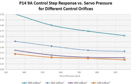
Operating with higher servo pressure will improve pump response as represented in the example chart below (showing a P14 size unit with 9A control). The chart also shows how changing the orifices in the servo stems can also impact control response. The .062 orifices are standard. The vertical axis of the chart represents seconds.
Hot Oil Shuttle (HOS) Valve
What is the purpose of the HOS?
The HOS valve serves to strip hot oil from the low-pressure leg of the loop to cool the system. The hot oil removed is replaced with cool fluid from the replenish / charge pump.
Where should I direct the hot fluid exiting the HOS valve?
To optimize cooling, the flow from the HOS should be plumbed to a cooler and filter before entering back into the reservoir.
What is the typical pressure setting of the HOS?
For standard Gold Cup drives circuits, the HOS is set at 200 psi (14 bar). When the pump is in the neutral position, the HOS valve is centered and inactive. During this time, both system legs will be regulated to replenish pressure controlled within the valve block. Replenish pressure is typically set around 75 psi (5 bar) higher than the HOS valve set point.
How much flow can I put through the HOS valve?
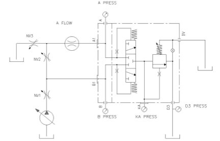
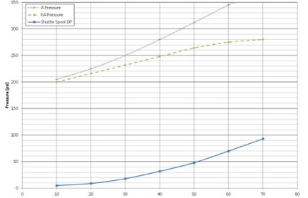
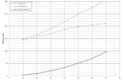
The valve can handle flows in excess of 60 gpm, however, the pressure drop across the valve can have negative effects the higher you go. Standard HOS valves will be factory set at 200 psi (14 bar) and the minimum shuttle pressure setting is 150 psi (10 bar). The test circuit and both associated charts provide the pressure drop across the valve (“A” Pressure dotted line) at various flows.
Is there an advantage of using the built-on HOS vs. using an external HOS?
The built-on HOS valve (specified within our P*S and P*L units) reduces plumbing complexity, customer assembly time, and minimizes leak points. For multi-pump systems, one large external HOS valve is sometimes considered over each pump having its own shuttle to minimize cost.
Replenish Flow (aka Charge Flow)
What is replenish flow used for?
Replenish flow (also called Charge Flow) is necessary in a closed-circuit design and provides two functions. Its primary function is to replace the loss of fluids in the system due to normal component leakage. In addition, this flow can be used for cooling the main system loop.
What happens if I have insufficient replenish flow?
Without adequate Replenish Flow, the inlet to the main pump will starve of the required fluid, resulting in cavitation and damage to the unit.
Where does replenish flow come from?
Most closed-circuit pumps are designed with an integrated “charge” pump, which is typically adequate to replenish the system fluid loss due to leakage. It’s not uncommon, however, to have additional replenish flow being supplied by a separate pump to assist with cooling.
What type of pump should be used if additional flow is needed for cooling?
Fixed positive displacement pumps (ie.. Gerotors, Gear, Vane) are well suited for replenish or make-up flow. A centrifugal pump should NOT be used due to its inability to respond quickly to system demands.
How much replenish flow is typically needed for cooling?
Flow requirements for cooling can change significantly depending on ambient operating conditions, duty cycles, and cooling methods/capabilities. As a starting point or general guideline, the replenish flow should be sized around 20% of the main system pump.
Replenish Pressure (aka Charge Pressure)
Why do I need Replenish Pressure?
A closed-circuit system relies on replenish pressure to assist with filling the pump throughout its rated speed range. Keep in mind that closed circuit pumps will not have a large suction/inlet port like an open circuit pump, so replenish pressure is needed to avoid cavitation.
What is the factory setting for Replenish?
The replenish relief valve on Gold Cups are typically set at 200 psi (14 bar). If the Gold Cup has the hot oil shuttle valve option, the typical setting is 350 psi (24 bar) or 480 psi (33 bar), depending on frame size.
What if replenish pressure is set too high or too low?
We do not recommend setting replenish pressure less than 150 psi (10 bar) as a minimum. Low replenish pressure can result in insufficient inlet requirements (cavitation) and would cause lower servo pressure (see Servo Pressure). Operating with elevated replenish pressure can reduce overall life of the replenish pump components. We do not recommend setting replenish pressure greater than 480 psi (33 bar).
How do I set replenish pressure?
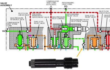
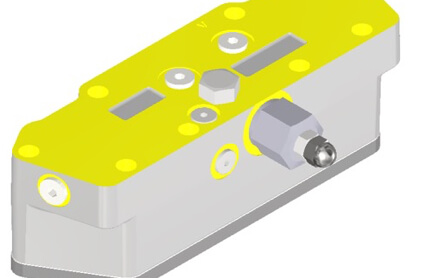
The replenish relief valve pilot stage is located within the valve block and free from risk of tampering. To make changes to the replenish pressure setting, the system must be shut down and non-operational. The pictures below show the location and pilot valve that needs removed to adjust. For adjustment procedures contact hps.technial@support.parker.com.
