

Arc of Motion
On this page, you'll find basic and advanced information regarding sizing and selecting arc of motion actuators.
Looking for Virtual Engineer?
START THE SIZING PROCESS
- Identify Motion Type: Determine whether the actuator will drive linear motion or Arc of Motion.
- Understand Arc of Motion: Arc of Motion refers to a lever arm traveling through a minor arc driven by a pivot-mounted cylinder.
- Select Arc of Motion: Choose Arc of Motion within the Arc of Motion Sizing tool.
KEY FEATURES
- Generate Results: After entering the minimum data requirements, the "Generate Results" button will become active. Press this button to initiate calculations for potential solutions.
- Compare Solutions: After generating results, the "Compare" button will activate, allowing you to compare the list of potential solutions.
- Save Progress: Use the "Save Progress" button at any time to resume your work later.
- Reset Parameters: The "Reset Parameters" option should only be used if you want to start over, as it will clear all entered data.
- Metric/Imperial Selector: Toggle between metric and imperial units for all inputs. You can also override this setting for individual inputs.
- My Project Section: Access the "My Project" button to store your information. Here, you can share your projects internally or externally with customers or suppliers.
Looking for more help? Download the detailed guide.
INPUT INITIAL DATA
- Review the Detailed Guide: Consult the detailed guide for information on all inputs, including descriptions and parameters. It is recommended to save this file for easy reference.
- Enter Operating Parameters: Input data for operating pressure, temperature minimum, temperature maximum, and tubing length.
- Adjust Default Values: The operating pressure, temperature minimum, and temperature maximum have default values that can be adjusted as needed.
- Mandatory Data Entry: The first mandatory data entry is tubing length, which is the distance from the valve to the actuator.
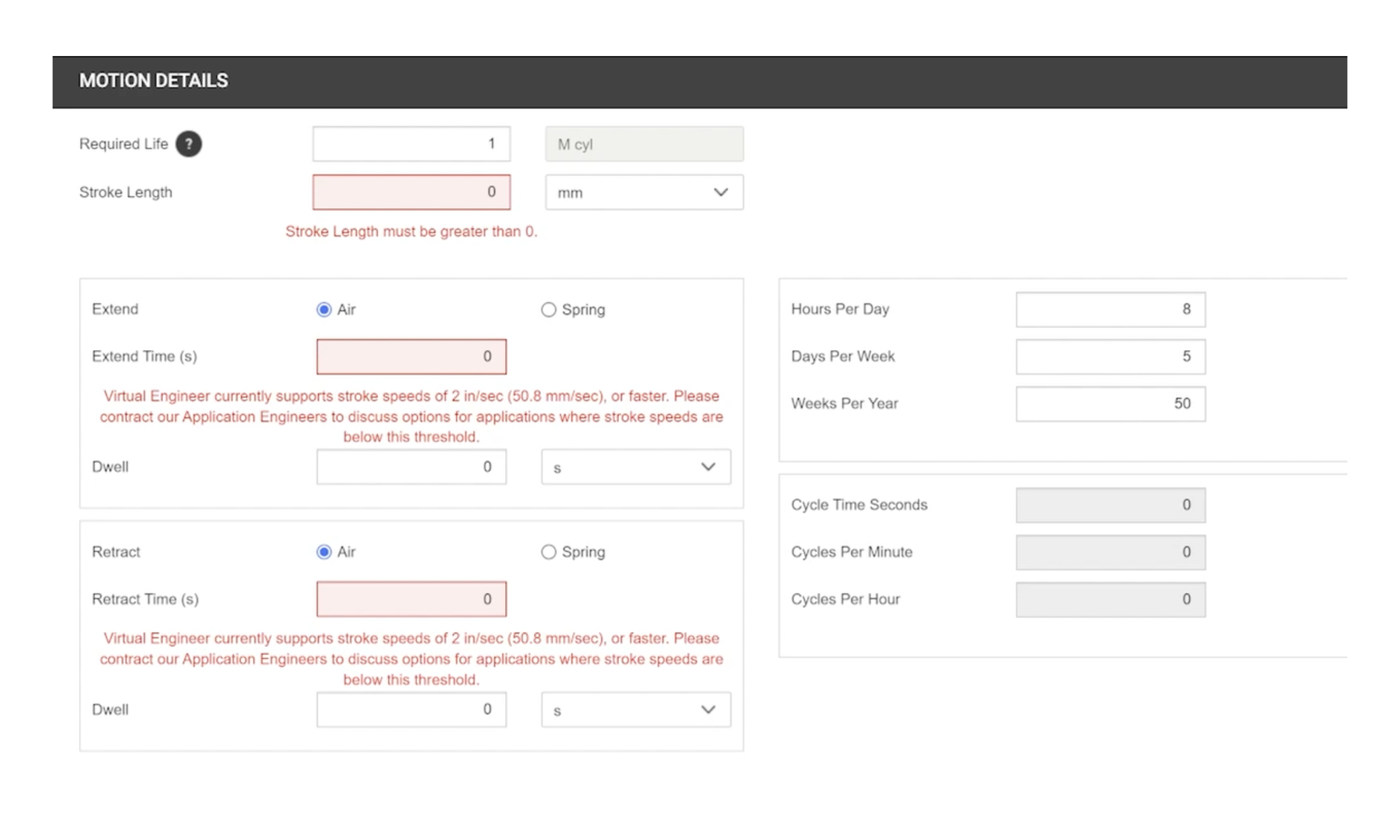
- Input Motion Parameters: In the Motion Detail section, complete the required fields, including required life, extend type, extend time, dwell time (if necessary), retract type, and retract time.
- Cycle Time Information: Hours per day, days per week, and weeks per year are pre-filled but can be adjusted. Cycle time, cycles per minute, and cycles per hour are calculated based on previous entries.
- Choose Lever Class: Select a lever class from the available options. The reference image will update to reflect your selection.
- Understand Lever Class Definitions: Familiarize yourself with the definitions of class one, class two, and class three levers based on cylinder, force load, and pivot point positions..
TIPS FOR THE DATA INPUT PROCESS
- Enter Input Values: Fill in the data cells, keeping in mind that red cells indicate required data.
- Input Lever Angles: Enter the lever start angle and finish angle from horizontal, noting that the cylinder is considered fully retracted at the start position.
- Define Distances: Input the distance from the pivot point to the cylinder attachment, the initial angle between the lever arm and the fully retracted cylinder, and the pin-to-pin retracted length available for the cylinder.
- Specify Force Parameters: Enter the distance from the pivot to the force, provide data for role orientation, and input the lever arm mass.
- Input Force Applied: Enter the force being applied to the lever that the cylinder must overcome, ensuring it is considered perpendicular to the lever arm.
GENERATING RESULTS & COMPARING PRODUCTS
- Generate Results: Once all required data points have been entered, select "Generate Results." The tool will perform extensive calculations to evaluate product performance.
- Select Products: If desired, you can select specific products to narrow down the results, but it is recommended to select all products for a comprehensive overview.
- View Comparison Table: When the "Compare" button becomes active, click it to see a list of all products that meet your application needs.
- Review Product Information: The comparison table will display part number strings, including series, bore, rod and bearing combinations, end-of-stroke options, and mounts.
- Evaluate Price vs. Performance: Use the comparison table to assess relative price versus cycle life, helping to determine if the added cost is justified for increased performance.
- Customize Comparison View: Click "Select Columns" to choose which information to include based on your project requirements.
- Generate Summary Report: Click the RPT button to obtain a summary report in PDF format that can be saved and shared.
VALIDATE DETAILS
- Manual Population of Rod Extension: Be aware that the calculated rod extension will need to be captured separately and manually entered in the Configurator.
- Review Mount Types: Consider adding the mount column to the selected columns in the table to review the type of mount needed for your application.
- Check Rod Extension: Pay attention to the Rod Extension column, which indicates how well the cylinder will fit the defined dimensions.
- Adjust E Dimension: If necessary, go back to the Arc of Motion input screen to adjust the E dimension and rerun the application until the rod extension is within an acceptable range.
FINALIZING YOUR SELECTION
- Configure Selected Product: Once you’ve decided on a product, click the "Configure" button to launch the Configurator.
- Pre-Populated Information: When you select a product, the Configurator will be launched with pre-populated information from the product you selected in the comparison table.
- Update CAD Model Preview: Click the update button to display and interact with your CAD model preview. It may take a few moments for the CAD file to load.
- Downloadable File Formats: Use the Formats tab to select from a list of downloadable file formats. Click the "Generate CAD" button to download your file.
- Save Your Project: Be sure to save your project by clicking the "Save and Proceed" button, which will take you to the My Projects section of the tool.
DEFINING GEOMETRY
- Choose Lever Class: Select a lever class. There are three traditional classes of lever and one torque generation class.
- Advanced Input Modes: Choose the CG Override mode for this example. In this mode, the lever class selection is unnecessary, as the parameters that determine lever class will be defined by you.
- Define Geometry: Begin defining the geometry of your application using the inputs labeled A through G, including lever arm mass and force applied.
- Understand the Application Plane: The application is defined in a 2-dimensional XZ plane, with the negative Z-axis aligned with gravity. The roll orientation input allows for rotation around the X-axis.
- Lever Arm Mass: Specify the mass of the lever arm, which is considered evenly distributed across its length.
ADVANCED INPUTS
- Advanced Mode Inputs: When the advanced mode is selected, three additional inputs appear. Input J allows you to define the shape of the lever arm, which can now include bends at the pivot point.
- Define Force Angle: Input K defines the angle of the force applied to the lever arm. This allows for the definition of any initial angle for the application of the force.
- Center of Gravity Override: When the CG override mode is selected, three more inputs appear. Input H defines the center of gravity's initial angle from horizontal, and Input I defines the radial distance to the center of gravity from the pivot point.
- Moment of Inertia: The Moment of Inertia override enables you to directly enter the moment of inertia calculated for the lever arm in your CAD model.

Need Assistance?
We're here to help.
For questions about Parker products or using Virtual Engineer, please contact technical support | pdn.technical@support@parker.com
To place an order or check the status of an order, please contact Customer Support | pdn.support@support.parker.com
For marketing-related queries, please contact the Parker Pneumatic Division Marketing Department | pdnmktg@parker.com
Visit Parker.com